OrcaFlex examples
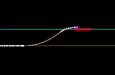
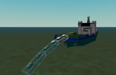
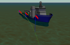
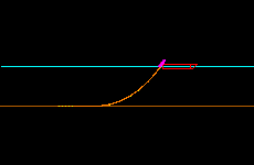
Pipelay and recovery
Below is a list of links to OrcaFlex example topics. Within each topic are a number of examples which each comprise one or more simulation files, a description pdf file, workspace files and sometimes other supporting files. The files for each example are zipped for easy download. The simulation files can be opened and viewed with the demonstration version of OrcaFlex.