
|
Mesh view |
|
|
Mesh view |
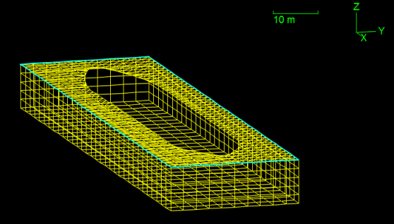
The mesh view shows an isometric projection of the mesh in which all objects are drawn as a series of connected lines – a wire frame. The mesh view is often the quickest and easiest way to check the spatial configuration of your model. More detailed information on the mesh geometry, and any warnings or errors detected by OrcaWave, are available on the validation and mesh details pages.
The pen colour, line width and style (solid, dashed etc.) for each type of object can be edited using the drawing data page.
The 3D view may be rotated, zoomed and panned using the view menu or the mouse and keyboard, to allow any aspect of the model to be viewed. A view may be printed, exported to a file or copied to the windows clipboard using the view menu, or from the popup menu.

| Figure: | A 3D wire frame drawing of a vessel mesh |
Use these check boxes to control whether an object type is included in the drawing (see the screenshot above). The same options are also available from the View | Draw menu and the popup menu.
| Note: | Some check boxes, e.g. to draw the control surface mesh, are hidden if the corresponding object type is not present in your model. |
Most of the view options are self-explanatory. Further discussion is only necessary for a small subset:
| Notes: | Multiple panels can have the same mesh file panel index. E.g.: panels obtained by reflecting mesh file data in a symmetry plane; different bodies using the same mesh file; if a non-planar quadrilateral panel has been divided in two; the wet and dry panels which result from clipping a panel that straddles the free surface. |
| Panels created by OrcaWave, e.g. if you selected to add interior surface panels, do not originate from a mesh file and do not have a mesh file panel index. |
| Tip: | In a multibody model it is sometimes useful to inspect the mesh one body at a time. This can be achieved by setting distinctive drawing data per body, or by temporarily unchecking the include box for other bodies. |

| Figure: | Mesh views for the same vessel. The top image includes the body surface, control surface, field points and sea surface. In the bottom image only the control surface is drawn. |
These controls allow you to highlight one or more panels in the mesh view. This is particularly useful for visualising panels associated with warnings or errors detected by OrcaWave during mesh validation.
You can measure distance on a 3D view using the measuring tape tool. Hold down the SHIFT and CTRL keys and then drag a line between any two points – the distance between them, in the plane of the 3D view, is displayed. The angle to the horizontal is also displayed, where horizontal is taken to mean horizontal on the screen, irrespective of the view orientation.